Python Docker Workflow 2

(This examples imply opinionated workflows or local configurations which may not apply to your case. Good projects have good documentation. ALWAYS refer to them for official positions of the projects themselves. The information here are for my own purposes, probably won't be updated to reflect the changes of the projects used and most likely will be outdated when you check it. Again, ALWAYS refer to the project documentation.)

There are two main ways of developing Python apps with Docker.

  • develop outside the container and, after it's done (there is no real done for software), copy all the project with a COPY directive in Dockerfile and regenerate the virtualenv based on requirements.txt
  • develop "inside" the container in a development container on a newly created volume and, after that, use this volume to create a production container

The first approach is easier and basicly documented by the Docker documentation itself. However, it's more error prone. Why?

(...)

The second approach is what I use:

The Dockerfile of the dev container:

# dev image
FROM fedora:28

WORKDIR /app

# needed to build scrapy and djangorestframework
RUN dnf -yq install redhat-rpm-config python3-devel gcc

RUN useradd -m -d/home/dbolgheroni -u1000 dbolgheroni
RUN chown dbolgheroni:dbolgheroni /app
USER dbolgheroni:dbolgheroni

EXPOSE 8000

CMD /bin/bash

Build the image:

$ sudo docker -t myproj:dev .

The Dockerfile is self explicative but the whys of this approach. Creating a Python virtualenv is prone to errors. Some modules involve compiling a lot of C files, which depends on compiling these files on a different platform.

Doing so in the container already helps you solve these problems earlier, not later.

Run container:

$ sudo docker run --name myproj-dev -it -p 0.0.0.0:8000:8000/tcp \
> -v /home/dbolgheroni/myproj/myproj/:/app/myproj/:Z \
> myproj:dev \
> /bin/bash

The Dockerfile for the production container comes later.

more ...

Python Docker Workflow 1

(this is too complex, disconsider. It's actually easier to use a temporary Dockerfile for a dev container)

(This examples imply opinionated workflows or local configurations which may not apply to your case. Good projects have good documentation. ALWAYS refer to them for official positions of the projects themselves. The information here are for my own purposes, probably won't be updated to reflect the changes of the projects used and most likely will be outdated when you check it. Again, ALWAYS refer to the project documentation.)

This article shows how to create a container without using a Dockerfile to test your dockerized apps:

To create the new container (yes, run creates the container):

$ sudo docker run -it \
> --name idigger-container-stage1 \
> fedora \
> /bin/bash

Add an user:

# useradd -m -d/home/dbolgheroni dbolgheroni

Commit:

$ sudo docker commit idigger-container-stage1 idigger-image-stage1

Create/run a new container to create the env:

$ sudo docker run -it \
> --name idigger-container-stage2 \
> -u dbolgheroni \
> -v /home/dbolgheroni/app:/app:Z \
> idigger-image-stage1 \
> /bin/bash

Enter the /app dir to generate the virtualenv (this is inside the container):

# cd /app
# python3 -mvenv venv
# source venv/bin/activate
# pip3 install django
# django-admin startproject idigger

Commit again:

$ sudo docker commit idigger-container-stage2 idigger

Create a new container based on the new image:

$ sudo docker run \
> -t \
> --name idigger \
> -p 0.0.0.0:8000:8000/tcp \
> -v /home/dbolgheroni/app:/app:Z \
> idigger-container-stage2 \
> sh -c '/app/venv/bin/python3 /app/idigger/manage.py runserver 0.0.0.0:8000'

To "enter" the container and make changes to it:

$ sudo docker exec -it idigger /bin/bash

Point the browser to the host port 8000 and voilĂ .

more ...

Debugging with python pdb module with stdin redirection from file

Debugging a program with Python pdb is trivial. You just run import pdb; pdb.set_trace() (or just breakpoint() introduced in Python 3.7), and the debugger will take action.

However, when the program being debugged has a stdin redirection, this is a source of trouble. This happens because your program may be reading, for instance, input with input() (which comes from file because of the redirection) and, when entering the debugger, it continues to read what is on the file as commands to Pdb, which almost certainly is not what you want.

More specifically, Python uses sys.stdin for functions such as input(). The pdb module, which contains Pdb class, uses the cmd module, which contains Cmd. Cmd, by itself, uses input(), which is why you have the behaviour described above. Pdb class accepts a stdin kwarg, but for Cmd to accept stdin, you must set use_rawinput to False, which is only set by Pdb when you also set stdout.

The most common shells has 3 file descriptors already passed to every command run from console, which are stdin (fd 0), stdout (fd 1) and stderr (fd 2). This comes from UNIX.

A common Python program reads its input (for instance, when you run input() to read the content a user might type) from fd 0, which the shell is telling stdin by default. When you run something like this

$ python3 <file.txt

the input of your program comes not from what you type, but from what it's in the file. In effect, the command above is the same as

$ python3 0<file.txt

at least for the most common shells.

So, to the solution. The first and the most obvious way is not to use stdin redirection but to open the file normally with open(). In this case, the file is hardcoded in the file. The second way is to read the file name from the command-line interface, but involves more boilerplate than the next solution.

The third solution is to read from another fd other than the 3 default fd's already supplied by default (see above). So you can use something like this:

import sys
sys.stdin = open('/dev/fd/3')

When using the debugger, as said above, you have to specify you're going to use stdin explicly. Otherwise, Pdb, which uses Cwd, will use what you set sys.stdin to. So, instead of import pdb; pdb.set_trace() as suggested by the documentation, do:

import pdb; pdb.Pdb(stdin=sys.__stdin__, stdout=sys.__stdout__).set_trace()

at the point you want to breakpoint. Don't forget to import sys if you didn't already done.

sys.__stdin__ is what sys.stdin is set when you run Python. Now, on the shell, to run your program, you do something like this:

$ python3 3<file.txt

and that's it. Now your program are reading the file from fd 3, and your fd 0 is freed to be used by Pdb.

more ...

Keyboard of the ThinkPad T430 on ThinkPad T420

Today I was able to replace a ThinkPad T420 keyboard with the one from the newer model T430.

T420 with T430 keyboard

Actually, it's quite common to see people doing the opposite: replacing the T430 keyboard with the T420's. The new ThinkPad 25 brings back this keyboard. But it's not a matter of preference, but of price.

This keyboard as a replacement part seems to became very rare to find with a reasonable price. A used one costs around U$120 and U$180 (Brazil). Just the keyboard. A used T420 costs around U$300. The whole computer.

I was able to find a new, T430 keyboard for around U$15, shipment included. At a reddit forum, I saw it was possible to install on T420 because of a customer who had the keyboard wrongly replaced by Lenovo.

With a cut here and a double-sided tape there, a few adjustments on .Xmodmap, we are set.

! ThinkPad T430
keysym XF86Back = Page_Up
keysym XF86Forward = Page_Down
keysym Next = Insert
keysym Prior = Delete
keysym Delete = Home

The backlit won't work, since there is no way to connect the power supply in it.

more ...

Install create-react-app

To install create-react-app without polluting all your base system with JavaScript files:

$ mkdir www
$ cd www
$ npm init # fill the fields, for almost all of them you can simply hit Enter
$ npm install create-react-app
$ export PATH=$PATH:$(pwd)/node_modules/.bin
$ create-react-app app

Curious thing about the JavaScript ecosystem:

$ ls -l app/node_modules/ | grep -c ^d
     889
$

Almost 900 packages for a basic web app.

more ...

JavaScript Object Inheritance Models

There are lots of ways to create objects in JavaScript and do inheritance, and the creativity usually extrapolates what I consider sane, but these are the ones that I use the most. I will call models here.

And note that this is ES5.

Pseudoclassical

JavaScript is a prototypal, class-free. The pseudoclassical is a way to give JavaScript a feel of the traditional object-oriented languages.

#!/usr/bin/env node

"use strict";

// constructor
var Car = function (name) {
    this.name = name;

    this.turn_on = function () {
        console.log('turn on');
    }
}

Car.prototype.get_name = function () {
    return this.name;
}

Car.prototype.turn_on = function () {
    console.log('push on');
}

// child constructor
var ElectricCar = function (n, bm) {
    this.name = n;
    this.battery_model = bm;
}

// inherit from Car
ElectricCar.prototype = new Car();

// augment child prototype
ElectricCar.prototype.get_battery_model = function () {
    return this.battery_model;
}

// instantiating
var lada = new Car('Lada');
var tesla = new ElectricCar('Tesla');

console.log(lada.name);
console.log(tesla.name);
tesla.turn_on();

Prototypal

The gist below uses Object.create(). Douglas Crockford, in his book JavaScript: The Good Parts, suggests augmenting Object in order to create a new object that uses an old object as a prototype. His proposal is:

if (typeof Object.create !== 'function') {
    Object.create = function (o) {
        var F = function () {};
        F.prototype = o;
        return new F();
    }
}

This isn't needed anymore. The book is from 2008. In 2011, ECMAScript 5.1 standardized it.

#!/usr/bin/env node

"use strict";

var lada = {
    name: 'Lada',
    turn_on: function() {
        console.log(this.name + ' on');
    },
};

var tesla = Object.create(lada);
tesla.name = 'Tesla';
tesla.recharge = function () {
    console.log(this.name + ' battery recharged');
};

console.log(lada.name);
console.log(tesla.name);
tesla.turn_on();
tesla.recharge();

Output

Both should output:

$ node file.js
Lada
Tesla
Tesla on
Tesla battery recharged
$
more ...

Generatig an OpenBSD miniroot for Cubieboard2

To generate an image for a Cubieboard2 based on the image available for the version 1.

Install ports for sysutils/u-boot and sysutils/dtb.

# pkg_add u-boot
# pkg_add dtb

Download the image for Cubieboard1 from your nearest mirror:

# ftp http://ftp.openbsd.org/pub/OpenBSD/snapshots/armv7/miniroot-cubie-60.fs

Use vnconfig to make your file appear as a disk:

# vnconfig vnd0 miniroot-cubie-60.fs

Mount the MSDOS partition and copy the dtb file for the version 2 of the board:

# mount /dev/vnd0i /mnt/vnd0i
# cp /usr/local/share/dtb/arm/sun7i-a20-cubieboard2.dtb /mnt/vnd0i

Write the U-Boot for the version 2 of the board:

# dd if=/usr/local/share/u-boot/Cubieboard2/u-boot-sunxi-with-spl.bin \
> of=/dev/rvnd0c bs=1k seek=8 conv=notrunc

Umount the partition and unconfigure the vnode disk:

# umount /dev/vnd0i
# vnconfig -u vnd0

Copy the image to the sdcard. Assuming that the sdcard appears as sd1:

# dd if=miniroot-cubie-60.fs of=/dev/rsd1c bs=1m

Insert into the board.

Done.

more ...

Arduino-like development with generic ARM boards and libmaple

Arduino is an open hardware board which allow manufacturers to clone its boards, as long as they do not use their original trademark. Leveraging the license, a lot of chinese distributors in fact do clone them, selling the boards for a very low price, making it available anywhere. They do not always respect the trademark thing, but that's another history.

Arduino wasn't the first open hardware board, but it was the first that gained widespread traction. It's convenient, and people like conveniences. Their main target are not engineers, but even they began to use it.

A lot of people, even longtime users, think of it as a standalone product, but don't know exactly how different parts fit each other. Arduino is a company1, a product, a board, an IDE, a library, a community, maybe something else also. But for the most part, Arduino is a library for a microcontroller (Atmel) which was on the market long before these boards were created.

The common microcontroller (Atmel) + library schema have some advantages. The library is a wrapper for a lot of features the microcontroller has. For instance, you do not need to know which register to poke to activate some port. Just choose the pin printed on the board, and the library knows what register is and what to move there. This approach has disavantages too. For instance, digitalWrite() is very slow. Some tests show it's even slower.

Another practical aspect is that this library can be used without an IDE. A lot of development boards use a modified Eclipse, which is complex, and bloated. Arduino IDE is simpler,Java-based, but do not offer much more than a very basic editor + a way to upload sketches. On the other hand, being open, some systems offer Arduino as commands to be used from the command line. For instance, OpenBSD has a devel/arduino package, which installs all the Arduino library environment, including its toolchain and a set of Makefiles that do the hard work for you. From nothing to the project uploaded to the board, it's a matter of 3 commands2.

Following these lines, some manufacturers began to use the same formula: open hardware board(s) + library (and maybe an IDE). One of these manufacturers is LeafLabs and its Maple boards. These boards use a ARM microcontroller based on STM32F103 from STMicroelectronics, which has a Cortex-M3 core. It's a much more powerful microcontroller than the ATmega328 used by the most common Arduino board. Faster CPU (72 MHz against 16 MHz), more Flash (128 KiB instead of 32 Kib), and so on.

LeafLabs also developed a library called libmaple, which is the core of what gives these boards pretty much the same programming API as Arduino. For instance, you can use digitalWrite() to turn a pin on on a Maple board too. Although Maple does have a IDE, very similar in form as the Arduino one, it has the same limitations.

However, LeafLabs boards are now longer produced. As with Arduino, some chinese manufacturers do clone them, making it very affordable, but there is an even cheaper alternative: generic ARM development boards using the same microcontroller. They can be made to work just a Maple Mini, but costing almost half the price of a cloned one, with the same features.

STM32F103

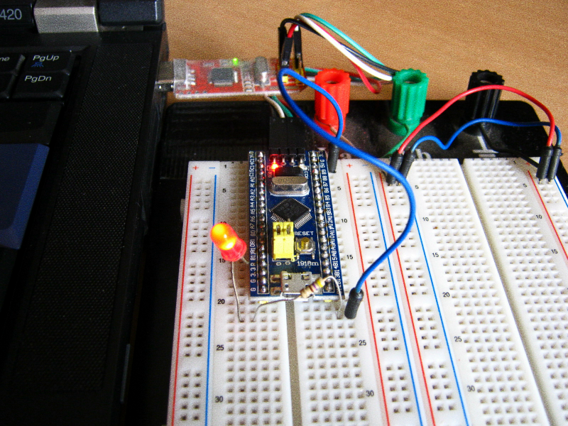
Burning Maple bootloader into a generic ARM board

The steps below are used to use a generic ARM board as a Maple Mini. A ST-Link/V2 debugger/programmer is needed and OpenOCD must be installed. A generic debugger is also cheap.

  • set pins (from debugger to the target board)
    • SWD are connected to IO
    • CLK are connected to CLK
    • VCC and GND to the obvious places
  • press reset on the target (board) and hold
  • $ doas openocd -f /usr/local/share/openocd/scripts/interface/stlink-v2.cfg -f /usr/local/share/openocd/scripts/target/stm32f1x_stlink.cfg
  • release reset button
  • $ telnet localhost 4444
  • press reset and hold and enter command
  • > reset halt
  • release reset button
  • > dump_image gen.bin 0x08000000 0x1ffff
  • download Maple Mini firmware
  • > flash write_image erase maple_rev5_boot20.bin 0x08000000
  • unplug target board from debugger and plug it directly (in OpenBSD, you'll see it attach as ugen (LeafLabs Maple 003)

The 0x08000000 didn't just came out of nowhere. This information is from the page 34 of the available datasheet.

openocd dump_image command saves the original firmware in case something goes wrong. flash writes the just downloaded Maple Mini image to the board.

Using it

The repositories for libmaple are on GitHub. It's a matter of cloning the repository.

$ git clone https://github.com/leaflabs/libmaple.git
$ cd libmaple
$ cp main.cpp.example main.cpp
$ gmake BOARD=maple_mini
$ gmake BOARD=maple_mini upload

A proper toolchain for arm-none-eabi toolchain is needed, and its binaries must be on $PATH. The dfu-utils utility are used to upload the binary to the board.

As said earlier, LeafLabs discontinued its boards and its libraries. There is an effort in supporting the old library called Rambutan, and the first command above can just be replaced by this:

$ git clone https://github.com/rambutan32/librambutan.git

Modify main.cpp and restart the iteration.


  1. Or companies, since this

  2. # pkg_add arduino; $ arduinoproject foo; $ cd foo; doas make upload 

more ...


rswtch

A switch to remotely power cycle development devices.

rswtch (front)

The problem: To develop for some boards like BeagleBone Black, Cubieboard 2 and Banana Pi, eventually a physical reboot is needed, either to reboot a freezed kernel or to develop low level features, within kernels or not.

This isn't too much of a problem on an environment of a good OS, where all kind of memory protections prevent wrong actions. When not above the confortable user level, one can't simply soft reboot because sometimes you won't even have a keyboard ready to accept commands. It's easy when the board is under someones nose, where a power cycling is easy to reset the board to a know state. However, it's very common to have to do this kind of development from a remote site, and without a remote switch like this, it is nearly impossible.

There are different products on the market that do power cycling. The ZY1000 JTAG debugger uses a relay. In their website, it's not clear whether they use a classic solenoid relay or some sort of a solid-state component. Some advanced PDUs (power distribution units) have this capability too, among others, like power metering, monitoring, etc. High-end computer systems, like servers, also have similar features, usually integrated onto the main board that holds the CPU. It's called BMC, and it stands for baseboard management controller. The latter are complex systems that do much more than just allow to reboot the computer. But unnecessary complexity is bad. Strive to solve problems with simple and elegant designs.

rswtch (on)

To the project itself, the goal was to have 3 channels, but not enough items were available at the workshop. The solution was to order some components for further assembly. The transistors used were 2 Darlington TIP102. In easy words, Darlington transistors have a very high gain, meaning it draws very low current from the microcontroller to make it work in the active mode (as a switch). The third not-assembled-yet channel will feature a MOSFET, either a IRFZ44 or a IRF3205. FET means field effect transistor, and in this type of transistor, there are no current drawing through its gate to bring it to the active mode. It can be driven by very low current ICs without a hassle.

Security considerations

Security is a concern. Since it can turn on and off the boards connected to it, you won't want anyone with access to your network to be able to do this. Although an Ethernet interface was considered, there are a lot of problems that must be solved in a microcontroller very very tiny flash RAM: authentication, cryptography, etc. Of course this is impossible.

Using this module connected directly through USB and accessing the rswtch built-in terminal ends up isolating the module to those who have access to the computer it's connected, which can be accessed (only) through SSH and leverage all the security of such approach.

Code

The source code of the firmware and the CLI utility can be seen here, as well with some operation details.

EDIT: There are some ramifications of this story based on some technical aspects.

How it was supposed to work, or how it was tested

Not all the details were shown on how this was tested. The plan was to have only one host with at least 2 USBs in a configuration as shown on the graph below.

rswtch - case 1

Index:

Just note the red arrows of the graph above. As it turns out, this didn't work as expected. Note that cb2 has 2 ramifications. If both ftdi and rswtch are connected to the USB ports of the same computer, we have one peculiarity which prevents this to work. The common configuration of most, if not all of the computers, is to have a common ground for the USB ports. This problem is also known as ground loop. This do not deserve too much detail, as it's not the point. However, it's important to note that because of this peculiarity, even if the channel is switched off by the rswtch transistor, ftdi keeps the lights on and maintains the USB 5V which rswtch were trying to shut down.

One solution is to add an USB isolator. Most of these are sold for industrial applications. As it's common, industrial usually means expensive, and although the robusteness of these solutions are attractive, the point here is to have something cheaper. There are 2 ICs which are commonly used to build USB isolators: 1) from Analog Devices labeled ADuM4160 and 2) from Linear labeled LTM2884. There are probably others.

So why worked at the first time? It was tested with this configuration:

rswtch - case 2

Note that the common ground is eliminated. However, one additional computer is used, which is of course undesired.

The third approach was to disregard the security implications explained above and add an Ethernet module on top of the microcontroller plus a very simple protocol on top of the UDP protocol.

rswtch - case 3

More on this later.

more ...