A switch to remotely power cycle development devices.
The problem: To develop for some boards like BeagleBone Black, Cubieboard 2 and Banana Pi, eventually a physical reboot is needed, either to reboot a freezed kernel or to develop low level features, within kernels or not.
This isn't too much of a problem on an environment of a good OS, where all kind of memory protections prevent wrong actions. When not above the confortable user level, one can't simply soft reboot because sometimes you won't even have a keyboard ready to accept commands. It's easy when the board is under someones nose, where a power cycling is easy to reset the board to a know state. However, it's very common to have to do this kind of development from a remote site, and without a remote switch like this, it is nearly impossible.
There are different products on the market that do power cycling. The ZY1000 JTAG debugger uses a relay. In their website, it's not clear whether they use a classic solenoid relay or some sort of a solid-state component. Some advanced PDUs (power distribution units) have this capability too, among others, like power metering, monitoring, etc. High-end computer systems, like servers, also have similar features, usually integrated onto the main board that holds the CPU. It's called BMC, and it stands for baseboard management controller. The latter are complex systems that do much more than just allow to reboot the computer. But unnecessary complexity is bad. Strive to solve problems with simple and elegant designs.
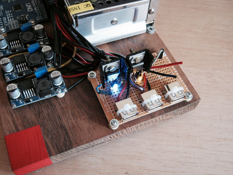
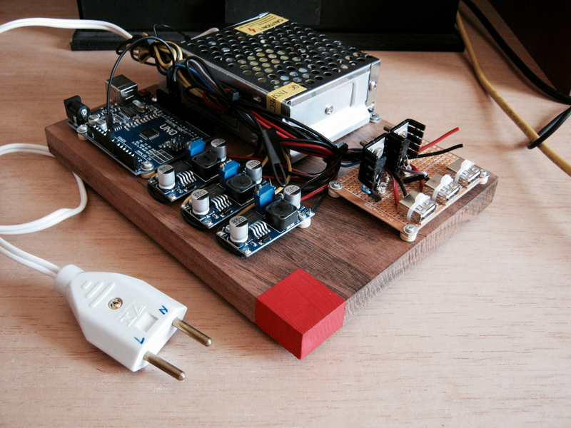
To the project itself, the goal was to have 3 channels, but not enough items were available at the workshop. The solution was to order some components for further assembly. The transistors used were 2 Darlington TIP102. In easy words, Darlington transistors have a very high gain, meaning it draws very low current from the microcontroller to make it work in the active mode (as a switch). The third not-assembled-yet channel will feature a MOSFET, either a IRFZ44 or a IRF3205. FET means field effect transistor, and in this type of transistor, there are no current drawing through its gate to bring it to the active mode. It can be driven by very low current ICs without a hassle.
Security considerations
Security is a concern. Since it can turn on and off the boards connected to it, you won't want anyone with access to your network to be able to do this. Although an Ethernet interface was considered, there are a lot of problems that must be solved in a microcontroller very very tiny flash RAM: authentication, cryptography, etc. Of course this is impossible.
Using this module connected directly through USB and accessing the rswtch built-in terminal ends up isolating the module to those who have access to the computer it's connected, which can be accessed (only) through SSH and leverage all the security of such approach.
Code
The source code of the firmware and the CLI utility can be seen here, as well with some operation details.
EDIT: There are some ramifications of this story based on some technical aspects.
How it was supposed to work, or how it was tested
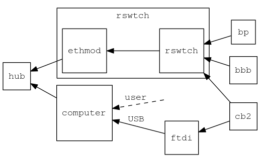
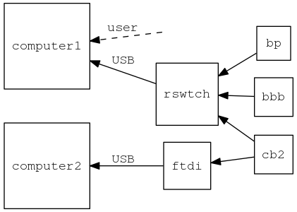
Not all the details were shown on how this was tested. The plan was to have only one host with at least 2 USBs in a configuration as shown on the graph below.
Index:
- bbb: BeagleBone Black
- bp: Banana Pi
- cb2: Cubieboard 2
- ftdi: USB-to-TTL serial module such as this
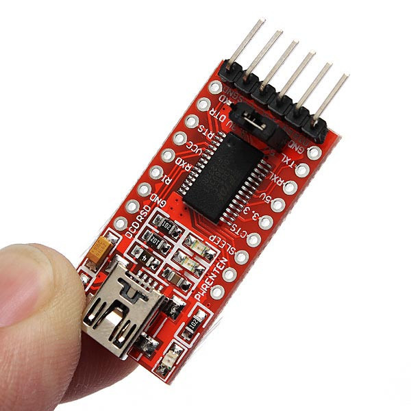
Just note the red arrows of the graph above. As it turns out, this didn't work as expected. Note that cb2 has 2 ramifications. If both ftdi and rswtch are connected to the USB ports of the same computer, we have one peculiarity which prevents this to work. The common configuration of most, if not all of the computers, is to have a common ground for the USB ports. This problem is also known as ground loop. This do not deserve too much detail, as it's not the point. However, it's important to note that because of this peculiarity, even if the channel is switched off by the rswtch transistor, ftdi keeps the lights on and maintains the USB 5V which rswtch were trying to shut down.
One solution is to add an USB isolator. Most of these are sold for industrial applications. As it's common, industrial usually means expensive, and although the robusteness of these solutions are attractive, the point here is to have something cheaper. There are 2 ICs which are commonly used to build USB isolators: 1) from Analog Devices labeled ADuM4160 and 2) from Linear labeled LTM2884. There are probably others.
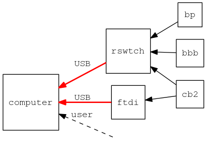
So why worked at the first time? It was tested with this configuration:
Note that the common ground is eliminated. However, one additional computer is used, which is of course undesired.
The third approach was to disregard the security implications explained above and add an Ethernet module on top of the microcontroller plus a very simple protocol on top of the UDP protocol.